IBM Control Panels
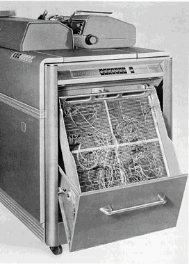
By the 1930s, most IBM punched-card equipment -- tabulators, accounting machines, multiplying and summary punches, calculators -- operated under the control of a plugboard, now formally referred to as a control panel. Users wired plugboards to specify exactly which card columns were to be read or punched, which card fields were to be fed to which accumulators, and so forth, depending on the machine. The instructions were given by connecting holes ("hubs") with wires. For example, a simple task on an accounting machine might be to print columns of numbers from a deck of cards, in which case a series of wires would connect card columns to printer columns. A slightly more ambitious version of this task would also accumulate totals by connecting the same card columns to accumulators, and then print the totals at the end. Eleanor Kolchin gives another example in a February 2013 Huffington Post Interview:
If I wanted to multiply, say, 12 times 15, I would punch a one and a two into the first column of a card and the second column of a card, then in the third column I would put another one and in the fourth column I would put a five. So the first two spots would be one and two and that would go into place on the plug board that shows it is the multiplier, and then the third and fourth spots on the card would go to a place that showed it was the multiplicand. And then there was a third slot that was to be the result, and that would punch the answer into whichever column on the card you wanted to put it in. And then you would need six wires to complete that.
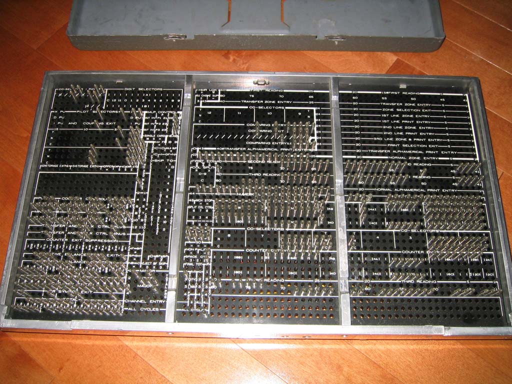
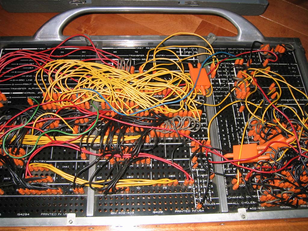
The following pictures were posted on alt.folklore.computers by Chris Shrigley, 22 May 2003, showing an IBM 402 control panel found in a neighbor's garage.
From Herb Grosch:
I wondered when I first saw [these pictures] what the widgets sticking up were. Dawned on me: those are the tips of the 'new' plugwires introduced with the 602 [my p.83]. In old plugboards like the 601 the wires plugged into a bronze clip behind the hole, and the other end of the clip contacted a prong on the machine. When you looked at the backs of old plugboards you saw a forest of identical clip ends. When you looked at the back of a new board you saw the tips of the wires plugged into the other side, which contacted the machine prongs [new shape, no doubt] directly. Nice engineering! This is what you see in the referenced picha. You also remind me the 407 had a four-panel (smaller panels?) board; I had forgotten.
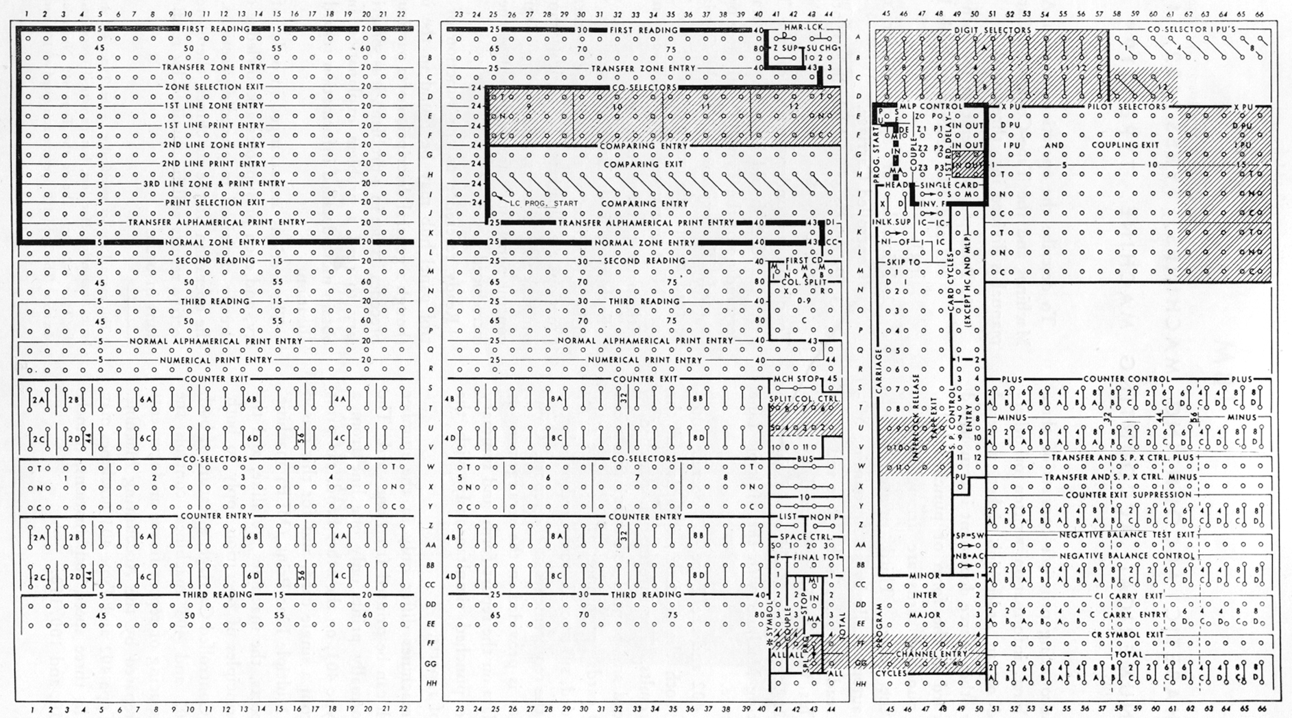
Each IBM machine -- tabulator, collator, interpreter, reproducer, calculator -- had its own unique control panel, and its manual would be filled with control-panel diagrams such the following:
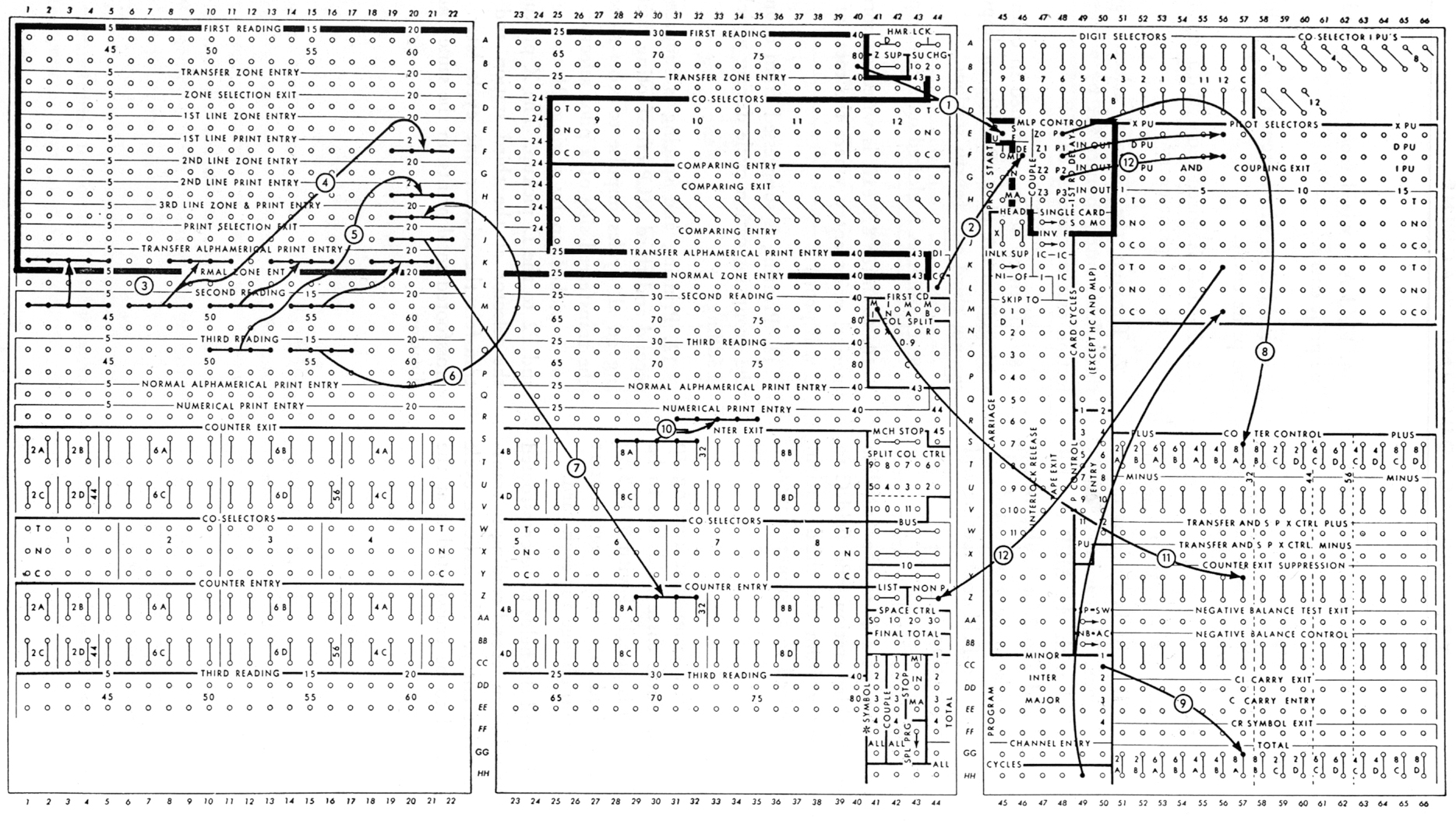
Computing courses, such as the one taught at Watson Lab by Eric Hankam had control panel templates printed on blackboards, so programs could be drawn over them in chalk.
- Basic Principles of Wiring IBM Accounting Machines, IBM, New York (undated), 114pp.
- IBM Accounting Machine Types 402, 403, and 419: Principles of Operation, International Business Machines: Eleventh Revision, Form 22-5654-11 (Copyright 1949, 1951, 1952, 1953).
Also see: Baehne [91] Plate 2, Hollerith Type III Tabulator, IBM 285, IBM 407, IBM 557.
Translations of this page courtesy of...
| Language | Link | Date | Translator | Organization |
|---|---|---|---|---|
| Belarusian | Беларуская | 2023/08/22 | Vladyslav Byshuk | Владислав Бишук | studybounty.com |
| Finnish | Suomi | 2023/08/31 | Kerstin Schmidt | writemyessay4me.org |
| French | Français | 2023/08/25 | Kerstin Schmidt | prothesiswriter.com |
| German | Deutsch | 2023/08/25 | Kerstin Schmidt | writemypaper4me.org |
| Italian | Italiano | 2023/08/31 | Kerstin Schmidt | admission-writer.com |
| Polish | Polski | 2023/08/25 | Kerstin Schmidt | justdomyhomework.com |
| Russian | Русский | 2023-07-16 | Alexey | Plastic Recycling Company |
| Spanish | Español | 2023/08/31 | Kerstin Schmidt | pro-academic-writers.com |
| Slovak | Slovenčina | 2023/08/22 | Vladyslav Byshuk | Владислав Бишук | studycrumb.com |
| Ukrainian | Українська | 2023/08/22 | Vladyslav Byshuk | Владислав Бишук | skyclinic.ua |
